Feeds:
Posts
Comments

Posts Tagged ‘photomicrograph’

Hard to believe, but this is my 100th post.   I thought about doing something serious, but honestly, let’s just go with what has been successful for me: garnets throughout my geology career

Garnets in plane light from the Northeast Kingdom of Vermont (BA research):

ERG-25b from the Cow Mountain region of Vermont; garnet inclusions are clearly at an angle to the dominant biotite-muscovite foliation in the rock

Garnet back-scattered electrons (BSE) image from the Connecticut portion of the Bronson HIll terrane (MS research):

BSE image of 99ERG07c

Girl Scouts participating in a Rocks Rock badge workshop (Western Kentucky University, 2002).   We ran the workshop in conjunction with both the Campus Girl Scout troop & the Geology Club the year I taught at Western.

Juniors (4th-5th graders) examining a garnet schist for the rock ID portion of their badge

Wavelength dispersive X-ray spectroscopy (WDS) images from a sample from Payer Land in northeast Greenland (or the PhD project I didn’t end up working on):

WDS mapping of 438965. Garnets are green in the Fe map, blue in the Mg map, and very light in the CP.

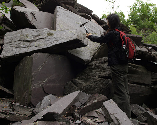
In-situ picture of the rocks I did work on for my PhD from Alp de Confin in Switzerland:

bimodal garnet sample that contains kyanite (hard to see without direct sunlight in these samples) from the Adula Nappe

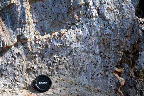
Outcrop photo from a 2007 Vassar field trip to Gore Mt in New York:

amphibole-pyroxene-garnet-plagioclase wall in the upper quarry at the Gore Mt mine

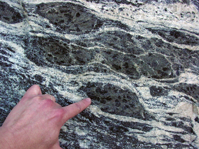
When I taught at the University of Pittsburgh at Johnstown, I started blogging.   At that time I started posting about photomicrographs, including one post about the “jellybean” mylonite from Payer Land.   Hmm, mylonites & garnets together 🙂

Garnet "fish" from the jellybean mylonite.

I started this blog when I moved from UPJ to Gustavus in the summer of 2010.  Over the course of the year, I posted several times during the year about garnets, but the most memorable to me is my summary of the 2010 GSA session in Colorado entitled “Garnet and Its Use in Unraveling Metamorphic and Tectonic Processes”.   Since I didn’t have any pictures to post the first time around, let me just say that garnet research is alive, well, and going in a multitude of directions according to that session.

And last summer I moved back to the Boston area.   Because I’ve only been teaching physical geology & solar system since moving, garnets haven’t come up much in conversation here recently.   In fact, my only garnet-related post was my submission to AW #43 earlier this week.   I obviously need to work on that!

pen & ink drawing of garnet gneiss from Best (1983)

So that’s a 100 posts.   Let’s hope I pick up the pace a bit, add a few more garnets, and hit 200 in less than 18 months 🙂

Read Full Post »

(I’m on spring break working writing like crazy on two papers, but I decided to take a bit of time and catch up on some blog posts I promised.)

Over a week ago while I was at NE-NC GSA in Pittsburgh, several tweets resulted in me promising blog posts.   Today’s sequence of posts is a result of Dana Hunter’s request to understand better how garnet schists form.   I was originally going to do this in one post, but its too ridiculously long.   Instead we’ll have this post on the theory behind metamorphic reactions.  A second on contact metamorphism of a shale.   And our final one on the formation of a garnet schist from a shale.

The base concept for metamorphic petrology is that thermodynamics tell us what should be present at any given pressure (P), temperature (T), water conditions, etc. (the item with the lowest energy = most stable), but kinematics gives us an idea how quickly a reaction will take place & whether or not the predicted phases will be present.   However, one of the most important thing to understand about metamorphism is that you have deal with the hand your dealt–the chemical components (Si, Fe, H2O, etc.) that are in protolith (original, unmetamorphosed rock) will either have to be in your subsequent metamorphic rock or leave the system in a believable fashion.   This is one of the reasons why memorizing the chemical formula of the common rock-forming minerals is actually useful–it gives you an idea about what could have been & what may have occurred to produce the rock now in your hand.

Before I move on to how the reactions work, let’s take a second and talk about “leave the system in a believable fashion.”   Some elements and compounds on our planet are very mobile and can move in & out of a system (a user-specificied volume that’s being studied).   When we metamorphose a rock, its easy to believe that these mobile components can drift in or out depending on the P & T conditions.   Other elements are relatively immobile and rarely travel any great distance.   In metamorphic systems, these are the elements we simply have to incorporate both in the original minerals & any subsequent minerals that form.

Frequently mobile components:

  • water (H2O)
  • carbon dioxide (CO2)
  • any other gases (Ar, methane, etc.)
  • Na+ or K+

Usually immobile components in metamorphic rocks:

  • Al3+, Cr3+, Ti4+, Si4+
  • Fe2+ or 3+, Mg2+, Mn2+, Ca2+

P&T will control how mobile an element is (hotter = more movement possible), but also the presence of fluid can make elements more mobile.   For instance, uranium is fairly mobile in the presence of a fluid phase — but there’s usually not much uranium in a rock to start with (usually in the parts per million (ppm) or parts per billion (ppb) range), so its not a huge concern when we try to balance a system.

Some general rules hold true:

  • colder rocks will generally have more fluid in them than warmer rocks
  • fluid is usually driven off during prograde (increasing T and/or P) metamorphism
  • when the fluid leaves or enters the system, it may have K+ or Na+ with it
  • during retrograde (decreasing T and/or P) metamorphism, the introduction of a fluid into a system may drive reactions that involve the formation of lower T&P minerals (retrograde minerals) at the expense of erasing the higher P&T mineral assemblages

As P&T changes along a prograde path, our rock looses water and/or carbon dioxide and some of the components begin to be less stable than a new group of minerals.   Though occasionally one mineral will simply switch to being a new mineral that is more stable, usually that instant switch is restricted to polymorphs (two different minerals with the same composition) that only need to change minor things in the structure (e.g. alpha-quartz to beta-quartz).   Most of the time, one (or more) mineral(s) will slowly lose an ion here and an ion there and a then new mineral(s) will use the released ions to grow.   These ions can either move around the outside of grains either with or without a fluid phase present or through a mineral–the latter is much slower, even though it might be a more direct path.

In the sequence of pictures above, thermodynamics dictated that the red mineral was no longer stable and that the purple mineral became stable at P2 & T2.   However, its kinetics that dictate how long it takes the red mineral to break down into its individual components (Ca2+, Si4+ and Al3+ in this case) and how quickly the purple mineral will grow.   Since the components have to diffuse (migrate from one location to another), there’s going to be some lag between when the red mineral breaks down and before the purple mineral starts to grow (picture #2).   The speed of the diffusion depends on:

  • temperature -> higher T’s = faster
  • presence or absence of a fluid phase -> fluid-present = faster
  • what the pressure is & whether or not its lithospheric (uniform in all directions) or differential (varies depending on direction) -> more complicated influence on diffusion, but minor compared to T & fluid-presence, so let’s skip on by for the moment
  • chemical gradients within the system; if one area is Ca2+ poor and another Ca2+ rich, then the Ca2+ will shift to try to get the Ca2+ evenly distributed throughout the system -> more of a difference between poor & rich regions = faster

If we had suddenly taken the rock after step 2 or 3 back up to the surface of the Earth, instead of preserving an equilibrium assemblage where all of the minerals are stable, we would have captured a moment of disequilbrium and a reaction frozen in its progress.   For most metamorphic analyses, equilibrium is what we are trying to find because we can calculate via thermodynamics what it should be.   However, in my mind, its the disequilibrium of frozen reactions that are more fascinating.

cordierite-staurolite-sillimanite-garnet schist from Vermont in PPL; several reactions were concurrently frozen creating the mix of non-ideal of grain shapes

I think that’s enough theory for now.   Let’s start dealing with a real rock.

Read Full Post »

(Part three following the basics of metamorphic reactions & contact metamorphism)

Ok, so now we want to make a garnet schist from our mud–I’m assuming this is a garnet-muscovite-biotite paraschist, since that’s what most people envision when they think garnet schist.   (I’m actually going to take this one step further and go all the way to a migmatite.)   Remember, we’re starting with a water-rich, Si + Al-rich protolith that has some Fe2+, Ca2+, Mg2+, Na+, and K+ as well.

In order to get a schist, we need to have foliated rocks, which are due to a differential pressure.   The most common cause of differential pressure is orogenesis or a mountain-building event.   An orogeny occurs when plate tectonics cause the collision of 2+ plates.   The rocks caught in the middle become squished and heated transforming from shales into a variety of foliated metamorphic rocks.   Almost all mountain belts in the world are due to orogenesis and most are composed of a mix of foliated metamorphic rocks, intrusive igneous rocks with associated contact metamorphic aureoles, extrusive igneous rocks, and a mix of sedimentary rocks from non-calm environments.

oldest at bottom, youngest at top–but note the basin closing & the rocks being trapped and therefore metamorphosed in the middle (http://image.absoluteastronomy.com/images/encyclopediaimages/a/ap/appalachian_orogeny.jpg) [disclaimer: this model of the Appalachian orogenies is out-of-date, though the concept is fine]

The mud to shale transformation will be the same, so we’re start with the shale.  This time we’re going to force the rock to undergo a differential stress (stress is simply pressure over a specific a specific area) concurrent with increasing the temperature.   Because of the differential stress, the existent minerals either rotate or grow parallel to the minimum stress direction.

unfoliated -> foliated development of elongate / platy minerals (http://www.tulane.edu/~sanelson/eens212/metatexture.htm)

At relatively low temperatures, the rock will become a slate.   Though harder & able to break more easily than shale, slates are still very, very fine grained so that individual grains of are not visible to the naked eye.

slate in PPL; the general assignment of grains elongate NW - SE is not blatant, but is visible (http://www.geolab.unc.edu/Petunia/IgMetAtlas/meta-micro/slate.UX.html)

As the temperature increases, more water is driven off.   Muscovite – KAl2(AlSi3O10)(F,OH)2 & chlorite – (Mg,Fe)3(Si,Al)4O10(OH)2·(Mg,Fe)3(OH)6 (both are micas) are now stable & start to grow large enough to be seen with the naked eye.   Quartz & plagioclase (NaAlSi3O8 – CaAl2Si2O8) are also stable, but difficult to see with the naked eye.   The new rock is called a phyllite, which will not break along planes that are as smooth as the slate.

phyllite in PPL (http://www.geolab.unc.edu/Petunia/IgMetAtlas/meta-micro/phyllite.UX.html) - oxides comprise most of the black material visible; foliation is much more visible & grain size has increased from the slate

Finally, we drive off enough water that we move from the land of phyllites with micas just barely big enough to see to larger grained schists.   Chlorite & muscovite are joined by biotite – K(Mg,Fe)3(AlSi3O10)(F,OH)2 and the grains are now larger.   The first schists aren’t very different from our phyllites, but once we start to break down chlorite, we start to reach some “exciting” rock – garnet schists.   (Garnets have a wide compositional range — the general formula is X3Y2(SiO4)3 where X = Ca2+, Mg2+, Fe2+, Mn2+, Y = Al3+, Fe3+, Cr3+.)

Garnet schist in the southern Menderes Massif, Turkey; the "shininess" is from the large muscovite grains; the "bumps" are garnet (http://www.geologist.nl/images/Turkey%202006/garnet%20schist.jpg)

garnet (clear, high relief in center) - muscovite (clear, moderate relief) - biotite (brown) schist from northeastern Vermont in PPL (quartz & plagioclase are the low relief, clear grains)

As we continue to heat the rock, the amount of micas in the rock decreases as we drive off more water & the percent of anhydrous minerals increases.   From garnet, we cross into staurolite ((Fe2+,Mg,Zn)1.5-2Al9[O6|(OH,O)2|(SiO4)4]) schist for a short period of time.   Though staurolite is hydrous, the amount of water needed for it is much less than the micas.

staurolite (black crosses) + garnet (equant bumps) + muscovite (shiny) schist (http://www.pitt.edu/~cejones/GeoImages/6MetamorphicRocks/Schist/SchistStauroliteCUp.jpg)

staurolite (pale-yellow) + biotite (brown) + muscovite (clear, moderate relief) schist in PPL (http://www.geolab.unc.edu/Petunia/IgMetAtlas/minerals/staurolite.UX.html)

As staurolite starts to break down, we’ve reached another critical point.   Our rocks are going to shift from containing a reasonable amount of micas to being comprised of a high percentage of anhydrous minerals.   One result of this shift is that we’re going to move away from schists that are mainly due to the alignment of platy micas and instead form gneisses.   A “gneissic” texture simply means that the minerals are banded with darker colored minerals (biotite, amphibole) together & lighter colored minerals (e.g. quartz, plagioclase) separated from each other.

sillimanite needles (clear, mod-high relief) wrap around other minerals; note how the biotite regions are segregated from the quartz + plagioclase sections (http://www.gsi.ir/Images/Gallery/Metamorphic%20Rocks/FullPic/2009-12-14_02.23.16_Sillimanite%20garnet%20schist%20with%20staurolite%20relics%201.jpg)

As first muscovite then biotite breaks down, the rock can take two different paths.   If the reaction occurs slowly and water just trickles into the system, the gneiss will simply become more & more anhydrous in a solid state until the granitoid-melting temperature is reached.

If the breakdown releases a relatively large amount of water into the system at one time while the rock remains at a high temperature, the rock may start to melt “early.”   The first things to melt will be the “light” colored minerals & when they solidify again, they’ll be called “leucosomes.”   The material that requires higher temperatures to melt will be the darker minerals and is referred to as “melasomes.”   The rock as a whole will be known as a “migmatite.”

migmatite from central Washington - finger pointing to garnet-bearing melasome (http://web.pdx.edu/~ruzickaa/migmatite-centralWA.jpg)

(I can’t find a reasonable photomicrograph of a migmatite–I’ll have to look around a bit.)

Let’s do a check on composition.   Our current rock is probably quartz + plagioclase + K-feldspar + sillimanite + garnet + amphibole / pyroxene / biotite + oxides.   Main components of the rock?  Si + Al.   Check.   Minor components?  Fe2+, Ca2+, Na+, K+, Mg2+.   Check.   Is losing most / all of our water reasonable?   Check.   Looks like we’ve successfully gone from our protolith to metamorphic rock compositionally.   (In reality, I should do a “real” balance–but that’s a bit overboard for here & now.)

Ok, so that’s mud -> migmatite.   Boy is this post overly long even after separating it into three posts–if anyone is still there & wants me to go through the metamorphism of a basalt, limestone, some other protolith of your choice, please just leave a comment.

Read Full Post »

I was sitting in a paleomagnetism talk at NE-NC GSA in Pittsburgh Sunday when the speaker put up a picture of several unidentified ore minerals & pyrite.   1) I had never seen a reflected light photomicrograph in a conference talk before [I don’t normally sit in paleomag sessions…] and 2) pyrite is this week’s choice!

So, what does pyrite look like?   In transmitted light, pyrite will be another one of the opaques (black both in PPL & XPL).

In reflected light, pyrite tends to be white to yellow-white to yellow in color.   It can be difficult to distinguish from chalcopyrite (stronger yellow color in the images below):

Pyrite (py) -chalcopyrite (cp) symplectites. Pentlandite (pn) & Pyrrhotite (po) also present. a) Symplectite in stringer sulfides from the Thompson 1D ore body. b) Symplectite in annealed massive sulfides from the Thompson T1 Mine. From Liwanag (2001) and Burnham et al., (2004). http://gsc.nrcan.gc.ca/mindep/photolib/ni_cu_pge/thompson/images/fig39.jpg

The small differences in color are frequently difficult to distinguish from each other:

Coarse-grained pentlandite (yellow-brown, centre and right) shows characteristic cleavage along (111) and is intergrown with pyrrhotite (pink-brown, lower reflectance than pentlandite, left and bottom right). Pyrrhotite has rims of pyrite (white, centre bottom) and chalcopyrite (centre) which has tarnished to a dull yellow. Minor amounts of pyrite form areas within pyrrhotite along crystal boundaries (top left). Dark grey areas are silicates and black areas are polishing pits.http://www.smenet.org/opaque-ore/

The central spinel phase is zoned with a lower reflectance core (light grey, centre) of chrome-rich spinel (ferrochromite) and a higher reflectance iron-rich rim (magnetite) (bottom centre). It is extensively shattered and the fractures are infilled with chalcopyrite. Chalcopyrite (yellow, left) is intergrown with pyrite (pale yellow-white, higher reflectance, right) and euhedral to subhedral highly altered pentlandite (light yellow brown, many polishing pits, top centre). Violarite (brown, top right) is the main alteration product of pentlandite. Dark grey areas are silicates. http://www.smenet.org/opaque-ore/

Pentlandite (light brown, centre) is intergrown with chalcopyrite (yellow, right), pyrite (pale yellow-white, centre bottom) and minor amounts of pyrrhotite (lilac-grey, centre right). Silicate gangue (grey) shows internal reflections. Black areas are polishing pits. The sulphides are interstitial to the silicates. http://www.smenet.org/opaque-ore/

I think the take-home message here may simply be: either get very good at distinguishing small changes in color & how reflective a surface is OR hope that your department has an SEM down the hall.   At Gustavus, we’re dealing with the former right now.

Next week’s mineral will be one that comes up time & time again here on my blog: garnet 🙂

Read Full Post »

Today’s mineral is a common sight to igneous and metamorphic petrologists, though how we ID plagioclase (or plag for short) in a gabbro vs. a garnet schist will vary quite a bit.

Plag varies from Na-rich (albite or Ab-rich) to Ca-rich (anorthite or An-rich) with complete solid solution between the two end-members.   The difference in composition is reflected in a variation between low refractive indices (Ab-rich) and “higher” refractive indices (An-rich).


Nesse (2009); Troger marks the diagram with quartz (~1.55), epoxy (~1.54), and orthoclase (~1.525) refractive indices for comparison

In PPL, plag is almost a dead-ringer property-wise for the K-feldspars, quartz & cordierite.   Plag is usually clear with low positive relief, though Ab-rich plag will have a low negative relief (see figure above).   Similar to the K-feldspars, plagioclase is more likely to alter to a clay (in this case a white mica called sericite), which you may be able to see in plain light as little dots or imperfections.   Though plag also has two good directions of cleavage like K-feldspar, because of the low relief we rarely (if ever) can distinguish the 90 degree planes.   In mafic igneous rocks, plagioclase is more likely to be lath-like than the other other clear, low-relief minerals, but tends towards more equant grains in felsic igneous & metamorphic rocks.


Clear mineral is plagioclase, brown is an orthopyroxene (opx); norite (yes, I renamed according to the IUGS classification!) from http://www.geolab.unc.edu/Petunia/IgMetAtlas/plutonic-micro%7F/hypgabbro.UX.html

In XPL, we can have more hope of distinguishing between plag and the other minerals–at least in igneous rocks.   Just like twinning is commonly found in igneous K-feldspars, plag also frequently is forms twins during growth from a magma.   In plag’s case, the twins are called “polysynthetic” and kind of look like jail bars.   Plag can also have simple twins (usually in very An-rich grains), but the polysynthetic ones are more common.

same norite as above, but in XPL; plagioclase is 1st order greys/whites with polysynthetic twins while the opx is 2nd-3rd order colors (TS is too thick): http://www.mpch-mainz.mpg.de/~jesnow/Ozeanboden/2001/Lecture3/iugs-gabbro-640.gif

same norite as above, but in XPL; plagioclase is 1st order greys/whites with polysynthetic twins while the opx is 2nd order colors (TS is too thick): http://www.mpch-mainz.mpg.de/~jesnow/Ozeanboden/2001/Lecture3/iugs-gabbro-640.gif


olivine (2nd - 3rd), clinopyroxene (cpx; 2nd-3rd - yes, at this scale we can't tell the diff), and plag laths (1st greys/whites with polysynthetic twins) in a diabase: http://www.geolab.unc.edu/Petunia/IgMetAtlas/plutonic-micro%7F/diabase.X.html

Plag has complete solid solution between the An & Ab end-members, but the diffusion between Na1+ & Ca2+ is fairly slow within a single crystal because the charge imbalance requires coupled substitution.   As plagioclase grows out a melt, the melt’s composition will change and become more enriched in whatever ISN’T being used by the plag (and anything else that is growing).   An crystallizes at higher temps, so the melt will be first depleted in Ca.   The next plag that grows won’t have the same ratio of Ca/Na to incorporate, so the next layer that grows will be more of a Ca-Na plag.   As this continues, each additional layer will be more & more Na-rich assuming that no Ca is magically injected back into the magma chamber.

We can actually see this in thin section, since each type of composition of plagioclase has a slightly different set of crystallographic axes (= varying refractive indices).   Each orientation of the specific plag compositions will have a slightly different extinction angle (almost all of which are non-parallel)–we look for the maximum EA possible in the thin section.

On the practical side, this means if the plag is zoned, we’ll be able to see the variation from core to rim.   We can also estimate what the composition of the plag is without trying to find an optic axis figure (which would also work if we note the change in 2V on the first figure way up at the top of this post), so that usually saves us some time.

zoned plagioclase crystal that was later fractured: http://www.geolab.unc.edu/Petunia/IgMetAtlas/minerals/plagioclase.X.html

On some occasions, the melt will manage to get back into the middle of the crystal.   That melt & the interior portion of the crystal are not thermodynamically at equilibrium with each other (which usually the rim & the melt are), so the interior starts to melt, while the rim remains untouched.   This can result in a “sieve” texture:

Ok, this works well for igneous plag, but there are some issues when we move over into metamorphic rocks.   The process of metamorphism usually either erases what zoning or twinning was present & plag that grows due to solid-state reactions doesn’t form twins, so plagioclase most common looks just like quartz, K-feldspar, or cordierite.   Luckily, cordierite is only present in low-pressure, high-temperature rocks & forms pleochroic haloes around U/Th bearing minerals, so we can rule that out quickly.   K-feldspar may occur in metamorphosed felsic igneous rocks, but is rare in metasedimentary rocks until high temperatures, so usually we don’t have to worry about it either.   However, quartz is almost everywhere.   And differentiating between quartz & plag in metamorphic rocks is probably one of the most annoying things to do with a PLM.

garnet (isotropic) schist with muscovite (2nd-3rd), quartz, plagioclase and biotite (2nd-3rd)--but which grains are qtz? which are plag?: http://www.geolab.unc.edu/Petunia/IgMetAtlas/meta-micro/porphyroblastic.X.html

There is some hope:

  • if the rock has been deformed, quartz may either have undulose extinction or subgrains — rare (if ever) in plag
  • if the thin section is slightly too thick, quartz has a tendency to become 1st order yellows instead of greys / whites (only very, very Ca-rich plag will become yellow)
  • quartz is uniaxial, plagioclase is biaxial–don’t hang your hat on this one, since we purposely cut metamorphic thin sections parallel to lineations & perpendicular to orientations, which makes finding an optic axis ridiculously difficult (if you have perp to both foliation & lineation, it works fine)
  • plagioclase may have deformation twins if 1) the rock has been deformed and 2) hasn’t been heated to >~400 C since the deformation; deformation twins aren’t as straight, tend to taper, and may only be in part of the grains in contrast to the polysynthetic growth twins in igneous rocks

Anorthosite (Ca-plagioclase) rock from Ceilidh Hill, central Australia; plagioclase contains deformation twins that bend, taper out, and terminate at cross-cutting twin faces: http://www.geo.umn.edu/orgs/struct/microstructure/images/047.html

  • if you’re lucky, the plagioclase has enough of a shift in composition between the core & rim that you’ll be able to see core-rim extinction differences–this is easy to mix up with undulose extinction in quartz unless you’ve been trained to look for it–unfortunately, I don’t have a digital picture at this point, though my master’s rocks from the Bronson Hill were filled with them; if I find time to scan, I’ll add one at a later time
  • at the end of the day, usually we end up taking our thin section and finding the closest SEM, because they are ridiculously easy to differentiate under an electron beam–this is part of that last 5% of nailing down what exactly is in the rock via more expensive methodology than the PLM

Next week, we’re returning to a mineral that most of you won’t recognize in thin section (which probably means Chris Rowan will be happy!): pyrite.

Read Full Post »

We’re back this week to a slightly unusual mineral to examine in thin section: halite.   In my copy of Tröger (there is an English translation, but its also out of print), halite (NaCl) is listed as mineral number 4.   Right up there with ice, lime (CaO), villiaumite (NaF), and sylvite (KCl).

Minerals 1 – 64 in Tröger are isotropic, which means that we’re only going to have to worry about properties in PPL this week.

(Finding photomicrographs of halite is not exactly easy.   Quite a few of the images I found were out of sedimentology papers and in black & white.   I’ve pulled what I can for color, but if someone knows of a good source, please add a comment at the end!)

In PPL, halite can vary from colorless, to a light blue-violet or yellow color.   Inclusions of fluid or air within halite are quite common, which can make the crystals appear “dirty” in thin section.   The refractive index of halite is 1.544, which is very, very close to the mounting epoxy, so halite will have a low relief and will make cleavage very difficult to see (even though halite has three perfect planes at 90).

(Black & white image, unfortunately.) Laminae of well-rounded, medium-sized quartz sand grains, inclined at approximately 30°. Interstices are partly filled with fine sand grains. Many grains are floating in halite cement. Cedar Hills Sandstone, 2016.6 ft. (Plane Polarized light, x 32). http://www.kgs.ku.edu/Publications/Bulletins/215/

Photomicrograph of an unirradiated sample (salt layer D, 423.3 m) showing primary fluid-inclusion-rich bands (c) and zones of clear halite (d). Clear halite commonly truncates fluid-inclusion-rich domains across sharp, curved, intracrystalline boundaries. Grain boundaries show up as dark curves in thin section. Secondary phases occurring at grain boundaries are anhydrite and polyhalite. Transmitted light image, image width is 2 cm.http://www.ged.rwth-aachen.de/Ww/projects/salt/IJES/SchlederUraiIJES2005.html
Photomicrographs of large, blocky halite grains with few fluid inclusion bands (see arrows). Dark lines are grain boundaries, the grey and red patches are anhydrite and polyhalite. Unirradiated sample from salt layer C (443.5 m). Image width is 3 cm.http://www.ged.rwth-aachen.de/Ww/projects/salt/IJES/SchlederUraiIJES2005.html

To examine the internal structure of halite, geologists may choose to irradiate the halite.   Images look ridiculously cool 🙂

Overview image of a thin section of sample gamma-irradiation decorated at 100 ºC from salt layer A (457.5 m), photographed in transmitted light. Grain boundaries occur as dark curves; white patches are fluid-inclusion-outlined chevrons and hoppers; and white polygons are subgrains. A few new, recrystallized, strain-free grains or grain regions are visible (see arrows). Image width is 4 cm.http://www.ged.rwth-aachen.de/Ww/projects/salt/IJES/SchlederUraiIJES2005.html

Photomicrographs show the microstructures of sample from salt layer A (457.5 m). Plane polarized transmitted light images of sample gamma-irradiated at 100 ºC. a) Migration of high-angle grain boundaries as recorded by elongated subgrains, and strain-free new material, which grows at the expense of old, heavily substructured grains. Image width is 11 mm. b) Strain-free grains grew at the expense of deformed ones. The size of some of the new grains is comparable to that of subgrains. Image width is 7 mm.http://www.ged.rwth-aachen.de/Ww/projects/salt/IJES/SchlederUraiIJES2005.html

Microstructures of sample from salt layer A (457.5 m, gamma-irradiated at 100 ºC), photographed in plane polarized transmitted light. In both images the grain boundaries occur as dark curves, while the white, milky areas are remnants of chevron grains. a) The clear, fluid-inclusion-free regions could be explained by a recrystallization mechanism of grain boundary migration. However, the presence of subgrains both in the chevrons and in the fluid-inclusion-free region implies that the structure is syndepositional and is a product of dissolution and precipitation processes. Image width is 16 mm. b) Similar structure as shown in image “a”. Milky, fluid-inclusion-rich (upper left corner) and clear, fluid-inclusion-free halite are separated by a sharp, curved line. The presence of subgrains in both the milky and clear parts is strong evidence that the structure was not developed by grain boundary migration. Note the serrated grain boundary at the right side. Image width is 1 mm.http://www.ged.rwth-aachen.de/Ww/projects/salt/IJES/SchlederUraiIJES2005.html

Ok, so who is looking at halite in thin section?   Halite can form as a cement in sedimentary rocks and also as the primary component in some evaporite deposits.   In the case of the group in Aachen (where most of the images above came from), the geologists are trying to discover how the halite has deformed over time to because it has implications for oil-bearing rock evolution.   In the image below, droplets of oil has been incorporated as fluid inclusions in the halite.

presence of oil aligned in “healed cracks” also indicates a stage of brittle deformation within the Ara Salt. The small micrograph proves the presence of oil by gas bubbles within the oil inclusion.http://www.ged.rwth-aachen.de/Ww/people/alumni/johannes/EGU/Talk.html

Before we come to an end, we should quickly discuss what halite might be mistaken for.

  • halite vs. quartz / feldspars / calcite -> halite is isotropic, all the others are anisotropic
  • halite vs. garnet (though why they would be in the same rock…) -> garnet has high relief vs. halite’s very low relief
  • halite vs. fluorite -> fluorite has a lower refractive index (1.43) than epoxy, so it will have a negative relief / Becke Line; also, fluorite is present mainly in igneous rocks where halite is unlikely to be found
  • halite vs. sylvite -> sylvite also has a lower refractive index (1.49) and that’s the best way to distinguish between them
  • halite vs. holes in the thin section -> this actually comes up as a problem, since halite may pluck out in the polishing process; glass / epoxy will tend not to have the bubbles that are frequently found in halite, but the refractive index is about the same; irradiation may really help this situation

Next week we’re going to talk about plagioclase, which means that the Michel-Levy technique will come up.

Read Full Post »

This week, we’re actually getting a three-for-one deal, since K-feldspar is actually just a shorthand to talk about sanidine, orthoclase, and microcline.   All three minerals have the same formula (they’re “polymorphs“), but in thin section they vary a bit.   Some of the properties will be the same across the board, but I’ll try and highlight the differences.

In plane light, the K-feldspars are very, very similar to quartz.   Usually clear, they can alter to clays and instead be cloudy or light brown in color.   The K-feldspars have a slightly lower refractive index that quartz, so while they also have low relief it can vary from slightly greater than the mounting epoxy (positive Becke Line) to slightly less than the mounting epoxy (negative Becke Line).   Though the K-feldspars have cleavage, their relief is too low to usually see the planes in thin section.

In XPL, we can start to distinguish between the three types.   Orthoclase & sanidine will frequently have simple twins (one side goes extinct at a different angle than the other).

same sanidine in the trachyte (XPL) that shows simple twinning; http://www.nslc.ucla.edu/pet/thins/jpgs/1.060.jpg

In contrast, microcline will frequently have two directions of twinning that look like a cross-hatch or a tartan.   (The twins are due to sanidine (highest T/P) & orthoclase (moderate P&T) changing their structure to the low T&P microcline.)   Unfortunately, authigenic microcline usually only has simple or no twins, which will make it more difficult to ID.

Also, as you go from high temperatures & pressures to closer to the surface of the Earth, sanidine can start to exsolve (at higher T’s, more Na can fit in the K-feldspar structure than at lower T’s–if the sanidine slowly cools, it may separate into two different minerals: one K-rich and one Na-rich).   The exsolved sanidine is called either perthite or antiperthite (former is K-rich surrounding Na-minerals, latter is Na-rich surrounding K-minerals).

    perthite with plagioclase (Na-rich) blobs within microcline; http://www.geolab.unc.edu/Petunia/IgMetAtlas/plutonic-micro%7F/perthite2.X.html

    (a brief search of the internet didn’t result in an antiperthite photomicrograph–if you see one, comment at the end!)

    Ok, how else might we distinguish between the three?  Now we get into problematic differences that are difficult to find:

    • extinction angles: if you can find an elongate mineral (good luck) or a crystal that has distinct parallel twins, we can measure whether the minerals go extinct parallel to NS or EW or at an angle; microcline ranges from 0 – 15 degrees, orthoclase 0 – 12 degrees, and sanidine 0 – 5 degrees–not much of a variation
    • biaxial optic axis figure: if you can find a circular section (even harder than finding an elongate xtal), all three of the minerals are biaxial negative, but they have different 2V’s: microcline is extremely difficult because of the twins, but is usually >65 degrees; orthoclase is normally greater than 40; and sanidine may appear uniaxial due to its very low 2V (<40 degrees)

    (If you don’t know what an optic axis figure is, I’ll cover that in two weeks!)

    What is K-feldspar usually confused with?   Actually, this is the same exact list as quartz, so just look back 🙂

    Next week?  Halite… not exactly a common mineral to examine with the microscope.

    Read Full Post »