I’ve decided to start back up my Photomicrograph Tuesdays series (look for the first installment tomorrow), but realized that there is going to be a fairly narrow audience because of the vocabulary & concepts involved. Last week, I managed to talk about stereonets by first explaining how they work, so I’ve decided to turn Mondays into a sort of “tools of the trade” guide for hard rock geology. Today, I want to talk about light in preparation for dealing with plane light microscopy in a week.
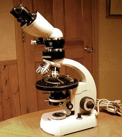
The petrographic microscope uses visible light that shines through a very narrow slice of a rock (~30 microns) to determine what minerals are present, their textural relationships to other grains within the sample, and in some cases an approximation of their chemical composition. The light comes up from the bottom of the microscope, goes through the slice of rock, then up through lenses until the intrepid mineralogy student can see what’s actually in the slice.

Visible light is about in the middle of range of possible electromagnetic (EM) radiation that is present in our universe. We use other types of EM radiation for different applications, like X-rays (shorter wavelengths) to see through people’s skin and radio waves (longer wavelengths) to communicate over long distances. Visible light itself is divided up into a number of different wavelengths that we as humans resolve as various colors. Red light, for instance, has a longer wavelength than blue light. White light is actually a combination of all the different visible light wavelengths, but for this application we’re only going to worry about using one wavelength, which is called “monochromatic light.”

If you’re a fan of the Big Bang Theory, you may remember in season 1 that Sheldon talks to Penny about how light acts both as a stream of particles and as a wave (I can’t remember the episode right now…). The stream of particles type of behavior is important for several types of analysis within geology, but for the petrographic microscope we need to focus on light acting like a wave.

Fig. 13.2 from Klein & Dutrow, 2008
However, light doesn’t simply move forward in one direction as a time, but instead has a wide range of light waves moving away from the propagation (forward motion) direction at the same time. This is called “unpolarized light” (see below). When using a petrographic microscope, its useful to control which direction of light actually goes through the slice of rock so we insert a filter between the unpolarized light source and where the slice of rock rests. The filter only allows certain orientations of light to get through, usually either those going EW or NS, though you could really set it for any direction you wanted. The filter is called a “polarizing lens” or “lower analyzer” (polarizing sunglasses work the same way) and the light that makes it through the filter is called “polarized light.”

So, now we have light coming out of a light bulb (or in really old microscope, they actually used sunlight / room lights reflected off of mirrors) and going through the lower polarizer on a microscope to become polarized light. Now the real fun starts!
The light hits the slice of rock, which has been mounted with epoxy on a glass slide. When waves go from one medium into a second medium, several things can happen. This is true going from air -> a mineral, or from the crust of the Earth -> mantle of the Earth, or from air -> water. What exactly happens will depend on the properties of both the first material and the second. The contenders are:
- reflection of the wave = this works exactly like a mirror works: the wave hits the interface between the two materials and bounces back; if the wave hits the interface exactly perpendicular to the surface (e.g. you standing directly in front of your mirror), the wave will return along the same path; in most cases, however, the wave is going to hit the surface at an angle and will be reflected back at an equal angle on the other side of the perpendicular line (or normal) to the surface; you can try this at home with a flashlight and a mirror–shine the flashlight at an angle at the mirror and observe where the beam ends up (try it from a few different angles to the mirror)

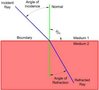
- refraction of the wave = when material one & two have different properties, when the wave hits the interface it may bend either into or away from the line perpendicular to the interface; whether a line bends in or out, will depend on the “refractive index” or “n” (ratio of the speed of light in that material divided by speed of light in a vacuum–higher values for more dense materials) of both substances; the relationship is called “Snell’s Law” and is: n1 * sin(incident ray) = n2 * sin(refracted ray); if n2 > n1, then wave will bend in towards the normal, but if n2 < n1, the wave will bend away from the normal; you can also try this at home by looking at how light behaves when you shine a light into the bathtub, because the water has a higher refractive index that air, so the light will bend in towards the normal (fishing cartoon below)


- absorption of the wave = part or all of the energy from the wave may also be absorbed by the materials its traveling into; this usually isn’t an important property for understanding how a petrographic microscope works, so we’re just going to quickly skip on by
In reality, all of these things are happening concurrently. Part of the wave is being reflected, part refracted, and part is being absorbed. But just as importantly, when a wave hits an interface, it may actually generate another wave.
The earth is made up of a number of materials, but they all act either “anistropically” or “isotropically” when an EM wave hits them. Isotropic materials have the same refractive index in all direction. When an EM wave hits them, it doesn’t matter what their orientation is, the wave is not going to split. Materials that are either amorphous (don’t have a regular symmetry pattern) or are very, very symmetrical will act isotropically. With anisotropic materials, however, the refractive index varies depending the orientation of the object. There is a range of possible refractive indices for each anisotropic material and that will influence how the object deals with an EM wave. It is possible to orient an anisotropic material so that it will be behave like an isotropic material, but its a special case & we’ll deal with that in a few more posts. For right now, let’s just focus on the non-special orientations. When a wave tries to enter an anisotropic material, it will be divided up into two rays that vibrate perpendicular to each other while both still trying to go in the same direction. This phenomena is called “double refraction” and is the main reason that the petrographic microscope is an extremely powerful tool.

In the above example, the light has divided into an “ordinary wave” (omega) and an “extraordinary wave” (epsilon). The ordinary wave travels in a straight line through the crystal, but the extraordinary wave does this funky thing disobeying Snell’s law and travels at an angle.

How far apart from each other the light waves manage to get is going to depend on the thickness of the crystal and what the difference in the refractive indices of the two different directions are. Thicker crystals will allow the waves more time to move apart from each other and will result in an observed larger double refraction. Same goes for the difference in refractive indices: large difference = large double refraction. Most minerals have a low to moderate difference in refractive indices and its hard to find a very clear, very thick crystal, so this can’t usually be seen with the naked eye. One exception is calcite, which has a large difference in refractive indices and only requires a clear crystal a few centimeters thick.


How do we know that the ordinary and extraordinary waves vibrate perpendicular to each other? We go back to the idea of polarization. If we were to take a piece of polarizing film (or a pair of polarizing sunglasses), we can manage to get one of the two double images in the calcite to disappear. If we rotate the polarizer 90 degrees, we can get the other set of double images to disappear:


This, by the way, is a great way to entertain a group of kids or college students. Simply give them a few clear calcite crystals, pieces of paper, pens to write on the paper with, and polarizing lenses and fun will be had by all!
Ok, so where are we at? We have light out of a lightbulb traveling up through the microscope and through a lower polarizer. The polarized light then enters our slice of rock and depending on whether or not the mineral is isotropic or anisotropic, the light will split into two directions. The light then continues on upwards and we have a choice. We can either filter the light again with the upper polarizer, which is oriented 90 degrees to the lower polarizer, or just let it go straight up through the magnification lenses to be seen by the geologist.
Let’s take out the slice of rock for a moment. In the first case, the light will be polarized in one direction (EW on the diagram below) and will come out of the top of the microscope with the same orientation, meaning the field of view will look bright. In the second case, the light is still polarized, but when it hits the upper analyzer (oriented NS on the diagram below) no light will get through because its at 90 degrees to the lower analyzer. The field of view will appear black. The second case will only be interesting if our original polarized light gets re-oriented as it goes through the slice of rock.

In the first case (called plane polarized light or PPL), we’ll be able to observe certain properties of the mineral (which I’ll discuss next week), but most of the effects of double refraction will be lost to us. In the second case (called crossed polars or XPL), double refraction is going to play a large role in the properties of the various minerals we can observe (two weeks from now). I’ll talk about when we use PPL vs. XPL as the weeks go by and what their strengths and weaknesses are.
I’ll also talk about reflected light microscopy as the semester goes on, which isn’t nearly as common as polarized light applications, but still is important especially when trying to look at economic minerals.
Intermingled with my mineralogy how-to posts, we’re also going to talk about a few more structural geology tools like cross-sections and Mohr Circles.

I just found your blog, and wanted to say thanks! The sections in this piece on birefringence clear up some of the questions I had when I was working on my own – more amateurish – article on the recent discoveries built around using calcite to make paper clips invisible (you probably saw the piece)… now I’ll have to go back and check to make certain that I got things right, but all in a good cause…
thanks for clearing my concepts in such a simple way
this was super helpful and extremely easy to understand. i love your figures as well! thank you.